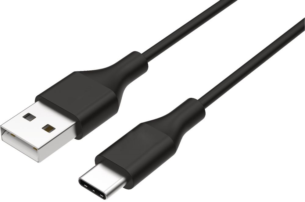
USB type A (Male) to USB type C (Male)
Almost all the new smartphones come with micro USB C. By 2024 all new smartphones and tablets sold (within the European Union) will require a common (USB-C) charging port and Laptops by 2026.
USB-C can be inserted both ways making it easier to connect. Having a common port will help significantly reduce e-waste and make it easier for devices to be charged and connected.
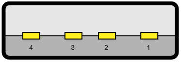
USB-A (Male) Pinout Table
| Pin |
Wire Colour |
Name |
Description |
| 1 |
Red |
VCC |
+5 Volts DC (Power) |
| 2 |
White |
D (-) |
Data (-) : Data from Device to Host |
| 3 |
Green |
D (+) |
Data (+) : Data from Host to Device |
| 4 |
Black |
GND |
DC Ground |
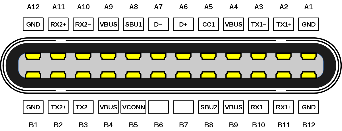
USB-C (Male) Pinout Table
| Pin |
Name |
Pin |
Name |
Description |
| A1 |
GND |
B12 |
GND |
DC Ground |
| A2 |
TX1+ |
B11 |
TX2+ |
Super speed data transmit+ (Host to Device) |
| A3 |
TX1- |
B10 |
TX2- |
Super speed data transmit- (Device to Host) |
| A4 |
VDD |
B9 |
VDD |
DC Power (+5V) |
| A5 |
CC1 |
B8 |
CC2 |
Power delivery communication line |
| A6 |
D+ |
B7 |
D+ |
Speed data transmit- (Host to Device) |
| A7 |
D- |
B6 |
D- |
Speed data transmit- (Device to Host) |
| A8 |
SBU1 |
B5 |
SBU2 |
Secondary Bus |
| A9 |
VDD |
B4 |
VDD |
DC power (+5V) |
| A10 |
RX2- |
B3 |
RX1- |
Super speed data receive+ (Device to Host) |
| A11 |
RX2+ |
B2 |
RX1+ |
Super speed data receive+ (Host to Device) |
| A12 |
GND |
B1 |
GND |
DC Ground |
USB-A (Male) to USB-C (Male) Pinout Table
| USB-A Pin |
USB-A Colour |
Description |
USB-C Pin(s) |
Symbol |
| 1 |
Red |
+5V (DC Power) |
A4,B4,A9,B9 |
VCC/VBUS |
| 2 |
White |
Data- (Device to Host) |
A7 |
D- |
| 3 |
Green |
Data+ (Host to Device) |
A6 |
D+ |
| 4 |
Black |
DC Ground |
A1,B1,A12,B12 |
GND |
| NC |
N/A |
Configuration Channel 1 (VBUS 5.6kΩ) |
A5 |
CC1 |
Notes:
- NC = Not Connected
- The 5.6kΩ resister is connected from the USB-C pin 5 to the +5V supply on the VBUS line.
- Outer conductive shielding is recommended for this cable to prevent unwanted RF interference.